
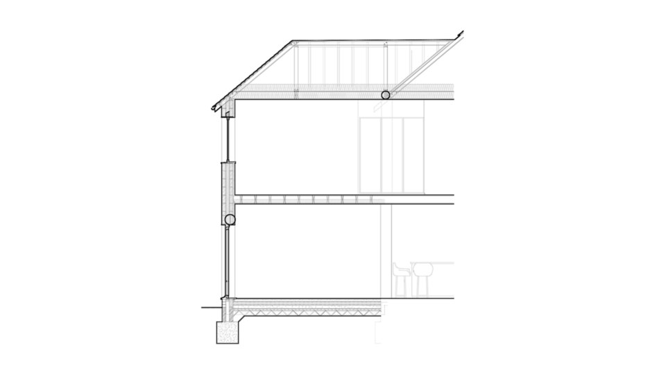
The simplest way to understand planning drawings versus building drawings is to look at a single sheet that only appears in the second set: the technical section. A planning drawing shows what an extension will look like. A technical section cuts straight through it and shows how every part will be built, from the concrete in the ground to the tiles on the roof.
This article explains one such drawing in detail: Section AA from the building regulations package for a two-storey rear extension we designed in Horley, Surrey. It is drawn at 1:20 and cuts through the new dining area on the ground floor and the new master bedroom above.
Why the section belongs to the building drawings
The planning drawings for this extension contained no sections at all. Plans at 1:50 and elevations at 1:100 were enough to show the council the size, shape and appearance of the extension and its relationship to the neighbours.
A builder and a building control officer need something different. They need to know what the foundation is made of, how thick the insulation is, how the new floor is supported and how the roof is ventilated. That information cannot be shown on a plan or an elevation, so the building regulations package adds sections drawn at 1:20, more than twice the scale of the plans, with written specification notes for every element.
Reading Section AA from the ground up
Foundations
The note reads: "Trench fill 1:2:4 mass concrete foundation to be taken down to a minimum depth of 1.000m below ground level or to match existing foundation depth if greater. All to be to the approval of the local authority building inspector."
In practice, the trench is dug and filled almost to ground level with concrete. The 1:2:4 mix (cement, sand and aggregate) and the minimum depth give the builder a clear starting point, while the words "or to match existing foundation depth if greater" prevent the new extension sitting on a shallower foundation than the house it adjoins. The section also marks the "assumed position of existing foundation", an honest acknowledgement that the existing footings will only be confirmed once they are exposed, and that the building inspector will check the trench before concrete is poured.
The ground floor
The ground floor is specified as a layered build-up, listed here from the top down:
- Floor finish to the client's specification
- Minimum 65mm reinforced sand and cement screed
- 500g polythene vapour barrier
- 100mm 'Celotex' (or equivalent) floor insulation, "turned up minimum 35mm at external perimeters to prevent cold bridging"
- 100mm reinforced concrete slab
- Radon gas barrier DPM, "turned up and lapped with full width of cavity wall"
- 50mm sand blinding
- 150mm compacted hardcore
Each layer has a job. The hardcore and blinding give a firm, level base. The radon barrier doubles as the damp-proof membrane and protects the room from ground gases. The insulation keeps heat in, and turning it up at the edges stops heat escaping where the floor meets the cold external wall. The screed provides a smooth, solid surface for the final floor finish.
Two further notes deal with the existing house: "new floor to line thru' with existing", so the new dining area and the existing kitchen sit at the same level with no step, and "maintain ventilation to existing sub-floor", so that the extension does not block the airflow beneath the original suspended floor.
External walls
The walls are specified as: "Sand and cement render on 100mm 'Fibolite' blockwork with 70mm 'Thermawall TW50' (or equivalent) allow 10mm clear cavity. 100mm 'Thermalite Turbo' blockwork with 52.5mm insulated plasterboard on dabs with skim finish."
Reading from the outside in, that is a rendered outer leaf of blockwork, a cavity partly filled with rigid insulation and a 10mm clear air gap, an inner leaf of lightweight thermal blockwork, and insulated plasterboard on the inside face. Together they keep the weather out and the heat in.
Two smaller notes complete the wall: "incorporate proprietary stainless steel wall ties at 450x750mm crs., 225mm centres at corners and reveals", which tie the two leaves together so they act as one wall, and "close cavities at door opening with proprietary insulated cavity closers", which seal the cavity around the new garden doors to prevent heat loss and damp.
Steel beams
Section AA cuts through two steel beams, labelled Beam 'B' and Beam 'C'. These support the structure where the new extension meets the existing house and the rooms are opened up to one another. The section shows their position; their size and connections come from the structural engineer, which is why the drawing states: "This drawing is to be read in conjunction with structural engineer's details."
This is one of the clearest differences between the two sets of drawings. A planning drawing shows an opening. A building drawing shows what holds the house up once that opening is made. Our guide to structural calculations for a house extension explains how the engineer's work fits alongside the drawings.
First floor
The new floor between the dining area and the master bedroom is specified as: "22mm T&G chipboard flooring laid staggered joint on 47x195mm C24 joists at maximum 400 crs."
The joists are strength-graded C24 timber, 195mm deep, spaced no more than 400mm apart, with tongue-and-groove chipboard laid with staggered joints for a stiff, even floor. The note continues:
- Joists are "fully nogged at maximum 2400mm crs.", with short timbers fixed between them to stop them twisting.
- Joists are doubled "beneath first floor partitions where required", where the weight of a wall above is concentrated.
- Where joists run parallel with external walls, "MS restraint straps at maximum 2.000m crs." are "screw fixed to minimum 3No. joists", tying the floor and walls together so each braces the other.
- "100mm acoustic quilt" fills the voids between joists, reducing sound passing from the bedroom to the dining area below.
- The ceiling below is "12.5mm plasterboard and skim".
On a single-storey extension none of this is needed. It is the second storey that brings the floor structure, the restraint straps and the acoustic layer into the drawings.
Pitched roof and insulation
The roof is specified as "plain concrete tiles to match existing on pretreated SW battens on 'Tyvek' (or equivalent) breathable felt on 47x97mm C24 rafters at max. 400mm crs." Matching the existing tiles keeps the extension consistent with the house, as the planning drawings committed to.
Below the rafters, "47x195mm C24 ceiling joists" align with the rafter positions and are "securely fixed to rafters at eaves". The voids between them are filled with "200mm mineral quilt insulation with additional 200mm layer over", a total of 400mm of insulation above the bedroom ceiling. The ceiling is lined with 12.5mm plasterboard and skim, and the note specifies "foil backed plasterboard to ensuite ceiling", because the foil acts as a vapour barrier over a room that produces a lot of steam.
To hold the roof together, "all rafters and joists to be nogged at max. 2.400m crs." and "wall plates to be strapped down walls at max. 2.000m crs.", so that wind cannot lift the roof from the walls.
Roof ventilation
The section requires "ventilation to roof space via eaves vent", equivalent to a 10mm continuous gap along the eaves, with further ventilation at the ridge, and asks the builder to "ensure retention of insulations at eaves to maintain ventilation to roof space". Air moving through the roof space carries away moisture that would otherwise condense on cold timbers, and keeping the insulation back from the eaves stops it blocking that airflow.
Flat roof
At the top of the extended roof, the section shows a flat section, specified as a "fully adhered EPDM rubber roofing membrane" on "18mm T&G OSB decking on pretreated SW firrings on counter battens on 47x97mm C24 joists". The firrings are tapered timbers that create a fall so rainwater runs off, and the note adds "flat roof supports with 47x97mm C24 framing. Ensure vertical timbers correspond with flat roof joist positions", so that loads pass straight down through the structure.
What Section AA gives the builder and building control
| Element | What the section specifies | Why it matters |
|---|---|---|
| Foundations | Trench fill 1:2:4 concrete, minimum 1.000m deep or to match existing | Stable support, no weaker than the house it adjoins |
| Ground floor | Screed, vapour barrier, 100mm insulation, slab, radon barrier, hardcore | Warm, dry floor protected from ground gases |
| Walls | Rendered blockwork, insulated cavity, thermal blockwork, insulated plasterboard | Weatherproof and energy efficient |
| Steel beams | Beams 'B' and 'C', to the engineer's details | Supports the house where it is opened up |
| First floor | 47x195mm C24 joists at 400mm, restraint straps, acoustic quilt | Strong, braced and quieter floor |
| Roof | Matching tiles, C24 rafters, 400mm insulation, ventilated roof space | Matches the house, keeps heat in and moisture out |
| Flat roof | EPDM membrane on OSB decking laid to falls | Watertight where a full ridge is not possible |
Every contractor pricing from this drawing is pricing the same thing. Every building control officer inspecting the work has a clear standard to check it against.
Why none of this appears on a planning drawing
None of the information in Section AA would help a planning officer decide whether the extension suits the house or the street, which is why it is not on the planning drawings. All of it is needed to build the extension properly and to have it signed off. That, in a single sheet, is the difference between planning drawings and building drawings.
For more on how a complete building regulations package comes together, see our guides to technical drawings for builders and the building control application for an extension. If you are still weighing up whether to build on one level or two, our comparison of single versus double storey extensions is a good place to start.
Book a Consultation
If you are planning an extension in Horley, Surrey or Sussex and need clear, buildable building regulations drawings, please get in touch with Adamson Architecture & Planning to arrange a free, no-obligation consultation.
Book a Consultation
For expert advice on all your planning and building control requirements, please get in touch to arrange a free, no obligation consultation.